
Building a desktop PC from scratch? Here are five tips to improve your build.
Getting started on your build
Building a PC is a great way to get a deeper understanding of how computers work. One pro is that it can be considered a more economical approach to getting a desktop for your unique wants and needs. Another pro is that it means you can take true ownership of something you will use every day, and get stuck in right away. You will finish the project with both a sense of pride and loyalty to your new creation.
We understand that building something from scratch can seem like a daunting prospect, but approaching it with a positive attitude will make the experience all the more rewarding. Once you do this, it will be easier to determine the unique aspects of your PC, having kitted it out yourself with all the appropriate tools for both work and play, including PC software tools for poker, or any other gaming you enjoy.
Here we’ve put together five tips designed to help make building your own PC a breeze.
5 tips for a better build
1. Before beginning, determine the purpose of the PC
Before you take on the challenging task of building a PC from scratch, ask yourself the reason for doing so. Do you want it to have the best gaming setup? Is it going to be used for your creative work? Or is it simply for casual web browsing?
Whatever your answer may be, the motivation for creating your PC should influence your decisions when you’re shopping for parts.
2. Choose between Intel or AMD
In order to get your dream build to the standard you want, it’s important that you do your research on the two main types of CPU that are available. For beginners, the CPU is the core of your PC, so your selection is a very important decision.
Remember, this isn’t the only part of a computer, so don’t waste your entire budget on it. You can’t go wrong with either of these brands, but which model you decide determines what sort of motherboard you can get, so be sure to do your due diligence before you make your final choice.
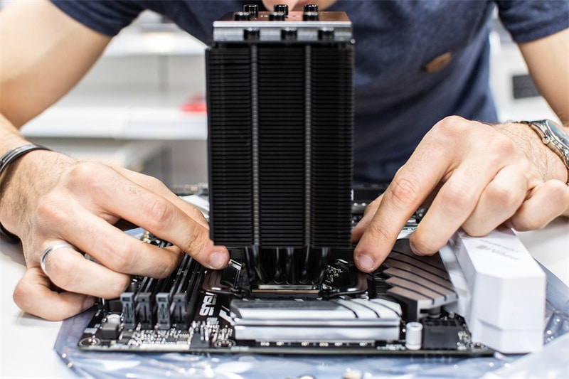
3. Make sure all the PC components are compatible
The components that you will need for the structure of your PC come in all shapes and sizes, and from a variety of different vendors, but that doesn’t mean that they will all work together. This is why researching each product before you buy is crucial for the overall running and maintenance of your PC.
For example, you’ll run into a lot of trouble if you’re in the middle of construction and you suddenly realize that your chosen motherboard doesn’t have the appropriate kind of socket for your CPU or SSD. And you’ll be in even more trouble if you get to this stage and don’t have enough budget to replace said incompatible components. Use your time wisely to read around about each product before making your purchase.
Think of your PC like an instrument: an instrument performs to the best of its ability when everything flows in harmony and everything works together to stay in tune with one another. Mismatched parts make an instrument unusable, and the same goes for a PC.
4. Keep your cables neat and tidy as you go
As you get deeper into the building process, you’re bound to be dealing with lots of cables. This will make it even harder to see around the case of your build. By keeping your cables organized and tidy as you go, you’ll find that when you’re done, your overall build will look much more professional.
Of course, you can always wait and fix the cables at the end, but why create more work for yourself when you can avoid any such headaches by carefully untangling cables beforehand and being vigilant when adding them to the cables already in place? A good way to do this is by placing zip ties around groups of cables, and creating space for other cables.
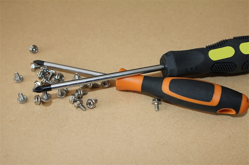
5. Organize your toolkit
Before you start to build anything, it’s important to make sure you’ve got the appropriate tools to complete every task. It should be possible to complete most of your build with a mid-sized head screwdriver, but we highly recommend that you invest in a well-equipped tool kit to deal with any screws or bolts that might be unique to your PC.
As we all know, screws can often be stubborn, so it’s better to be as prepared as possible. And if you really want an easy life, you could even think about treating yourself to an electric screwdriver!